

USB has always been multiple standards in a trenchcoat. USB-C has done nothing to help that, and even really good hardware organizations get it wrong. OnePlus got the specs on their USB-C charging cable wrong in 2015. Raspberry Pi 4 shipped with a faulty USB-C charging port in 2019. However, despite all its faults, I’ve come to appreciate how amazing USB-C really is, and the EU agrees.
USB-C, or USB Type C only indicates the port, not the protocol or standards underneath that need to be followed. If you spot a USB Type C port or cable in the wild, it could be for any or none of the following purposes:
- Charging without any negotiation, almost certainly 5V
- USB-PD (Power Delivery), where devices negotiate their capabilities and charge at different voltages
- Thunderbolt 4, where you have HDMI, USB-PD, legacy USB, etc. all rolled up in one
- Non-standard thunderbolt-like protocols, like on the Nintendo Switch
Scratching my head over USB-C protocols isn’t the topic of this post, but as a casual hardware maker who wants to put USB-C on all the things, this is important. Before I understood the nuances of USB-C, I made a few devices with these USB-C ports:
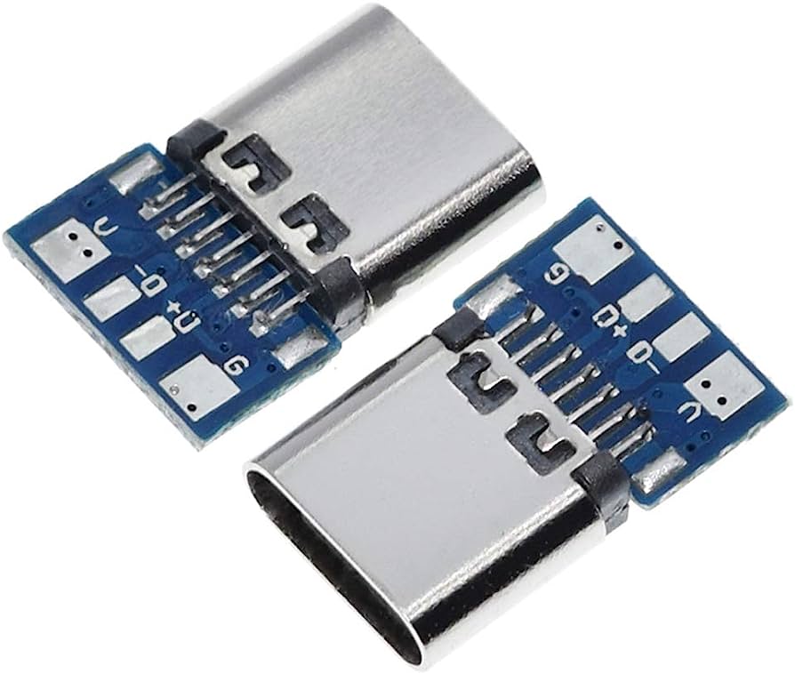
My assumption was that the manufacturer of these ports took care of whatever needed to be taken care of, and I could just solder wires to the pads on these, and power my devices. However, through the magic of USB-PD, only dumb chargers that did not do negotiations worked on my devices. This led to people asking me “Hey, device doesn’t work with my Mac charger” or “Are you sure you know what you’re doing?”. Well, I mostly ask myself these questions on a daily basis (unrelated to hardware).
Then there’s this guy:
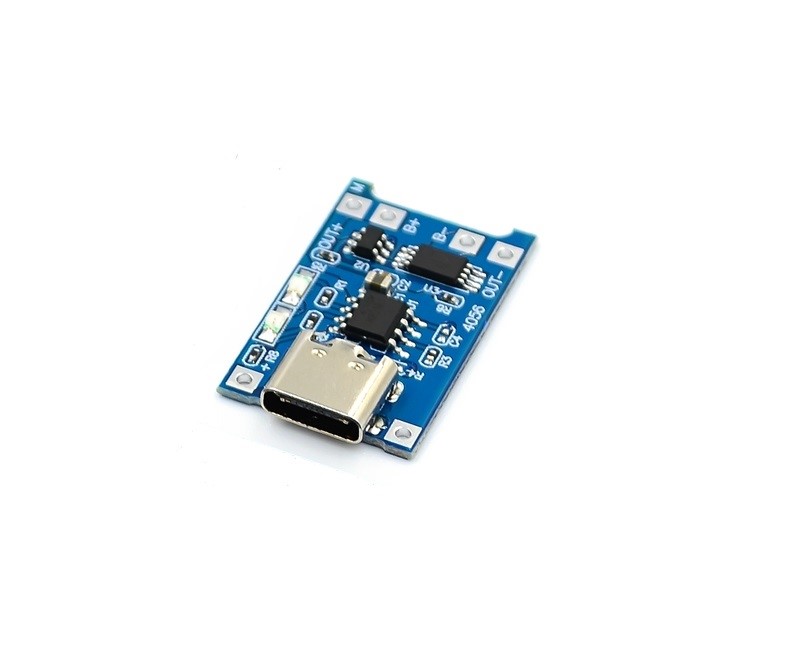
If you want to build portable devices that run off 18650s, they need to be charged, and the TP4056 chip has been the marker’s go-to charger for a long time. The version here is one with a Type C socket. Once again, I was happy at how easy it was to include USB-C charging capabilities, and disappointed that these professionally made charges also didn’t do USB-PD. The TP4056 also has a limitation on the charging speed being capped at 1A.
My search for a better charger led me to this:
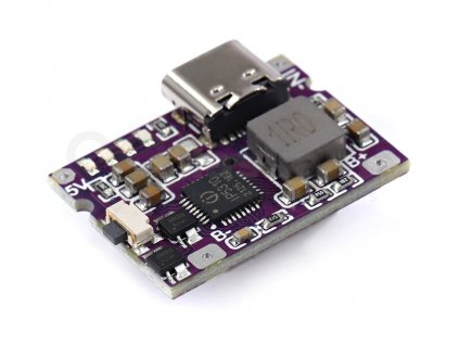
I don’t trust AliExpress component specifications, and usually turn to Reddit or the manufacturer’s product spec sheet. In this case, Reddit had no answers for my casual level of hardware knowledge, and I could only find the spec sheet for the actual IC (IP5306), but not this module. When this happens, I usually just buy the component and play around with it, which is often a much faster way for me to learn things. However this module had an issue - while the TP4056 will deliver power to any connected device, the IP5306 requires a button press. The button on this module was on a side perpendicular to the side with the ports. This meant one of two things:
- Solder another button to the same terminals and place it where I want
- Design the device to match the charger
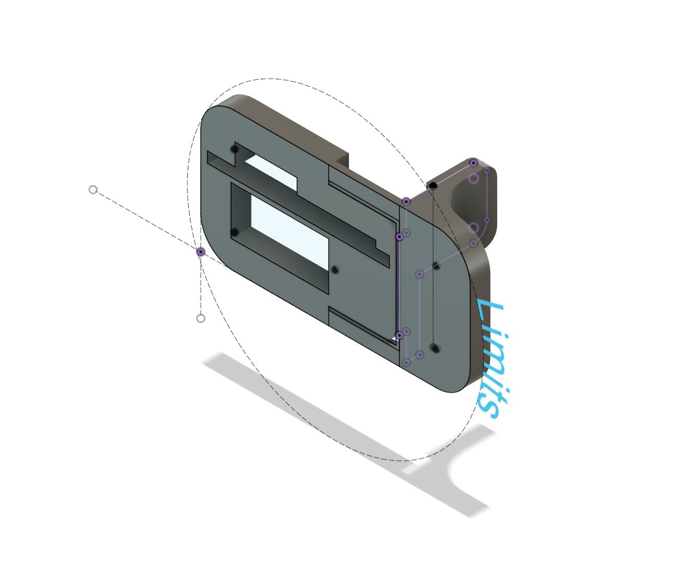
I went with option 2 for an LED matrix panel build since I had the room, but for my OpenLights Beacon project I didn’t have the room, so I had to pursue option 1. But that got me thinking - what would be a good design to support a push button? It had to be 3D printed, and ideally reduce the effort to assemble this charging module into the Beacon. Another realization quickly hit me - if I was going to design an assembly for the module, why not try to make it so that I could still press the existing button? The benefits were:
- Lesser components to solder and mount and tinker with
- Only have to design one assembly, instead of one for the charger and one for the button
But the challenges were:
- The user would be pressing in from the side with the port, but the button was perpendicular to the direction of action
- Intricate designs are not something you can 3D print with an FDM printer
- It had to be as reliable as a dedicated button without any additional components
There were three ideas that came to mind (I am not a Mechanical Engineer, these probably have a more scientific name):
- A bending action that would push the center horizontally when the object is compressed vertically
- A L-shaped crank pivoted in the middle that could push horizontally when pressed vertically
- An incline plane that would push a wedge horizontally against the button when the wedge is pressed in the vertical direction
From here, I’ll refer to the 3D printed mechanical button as MB, and the existing electronic button as EB.
Idea 1
I designed a housing for the charger that would allow me to install the MB later. Then I designed the MB with the following assumptions:
- The flex needed to press the EB would be minimal
- PLA (the filament material for my 3D prints) flexes just fine
First print
Off the print bed, it looked great. But the moment I tried pushing it into the housing, I noticed that my assumptions about PLA were not quite accurate. I had to flex it quite a bit to push it into the housing, and the MB stayed deformed inside the housing. But since the mechanism also relied on the EB pushing back when the MB is not compressed by the user, I assumed this would be OK. I pressed the module in place and realized the following:
- PLA really does not flex that much
- The EB could not provide the force needed to correct the deformation of the MB, so they both stayed pressed
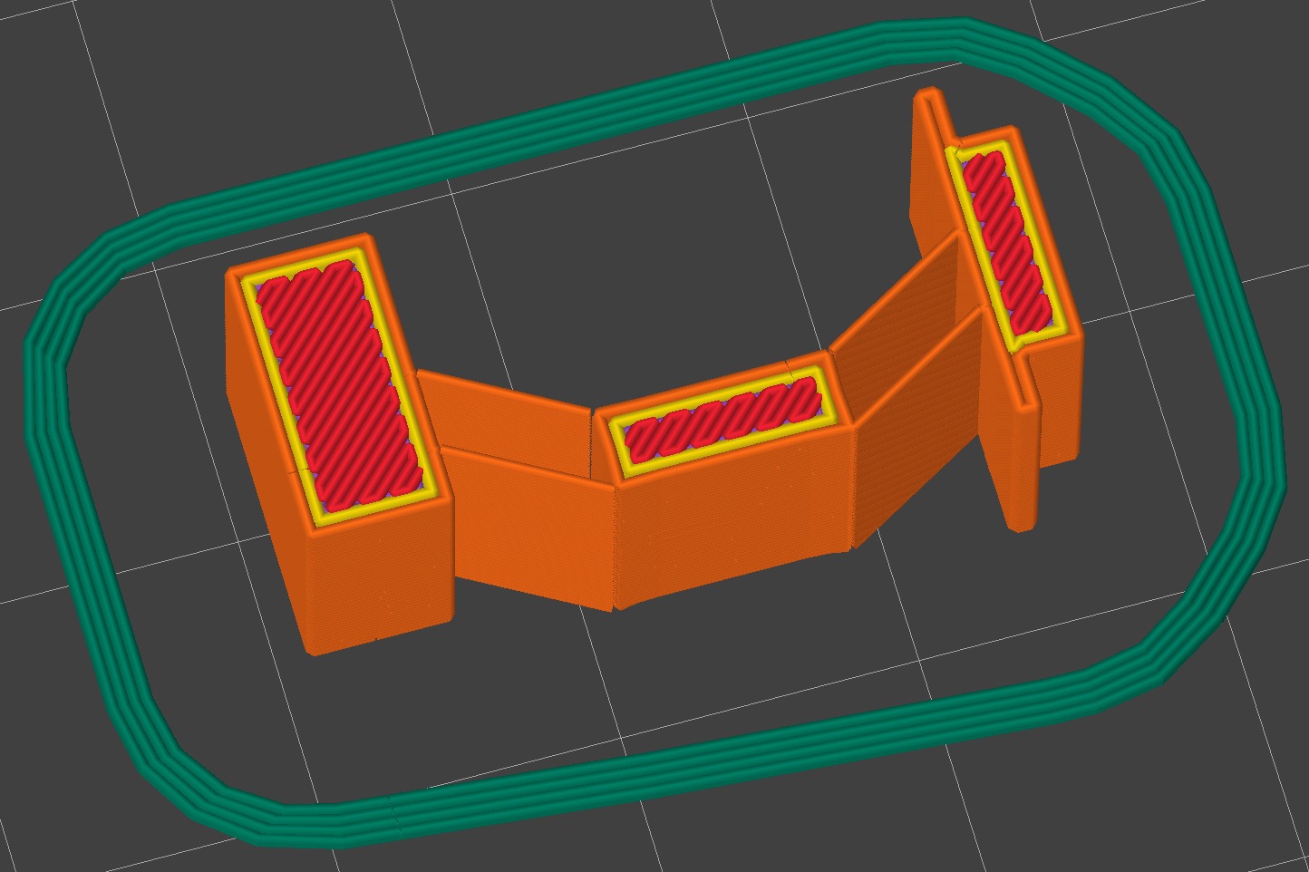
- The amount of horizontal motion generated depends on the angle of the bend. The illustration below might make that clear:
Notice how the horizontal motion is slower when the pin is closer to the horizontal plane, and faster when the pin is closer to the vertical plane? My first design was not at an optimal angle, which meant I needed a lot of flex to get miniscule amounts of horizontal motion.
Second print
3D printing is slow. So while my mind’s racing to give me several ideas, executing on those ideas takes at least 20 minutes between prints. For the second print, I decided on a few improvements:
- Make the flex angle steeper to achieve greater horizontal motion with lesser vertical motion
- Reduce the thickness of the connection to flex more easily
I took the print off the bed and compressed it to check the flex and it immediately collapsed in a way that’s obvious now, but not when I was designing it. New realizations:
- The connections were too flimsy to reliably compress instead of just folding randomly
- There’s nothing stopping the rotational motion of the vertical extremes
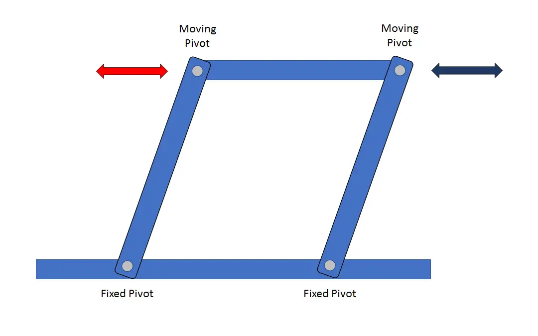
I realized I’d need what’s known as “parallel-motion linkage” to remove the possibility of the rotation and bending, and perhaps having two connections might increase strength as well.
Third print
It was getting late and I was getting slowly annoyed about PLA. Perhaps TPU would be better? Pushing aside my Hal-like tendencies, I printed my next design with the following improvements:
- Parallel-motion linkage
- A renewed sense of purpose
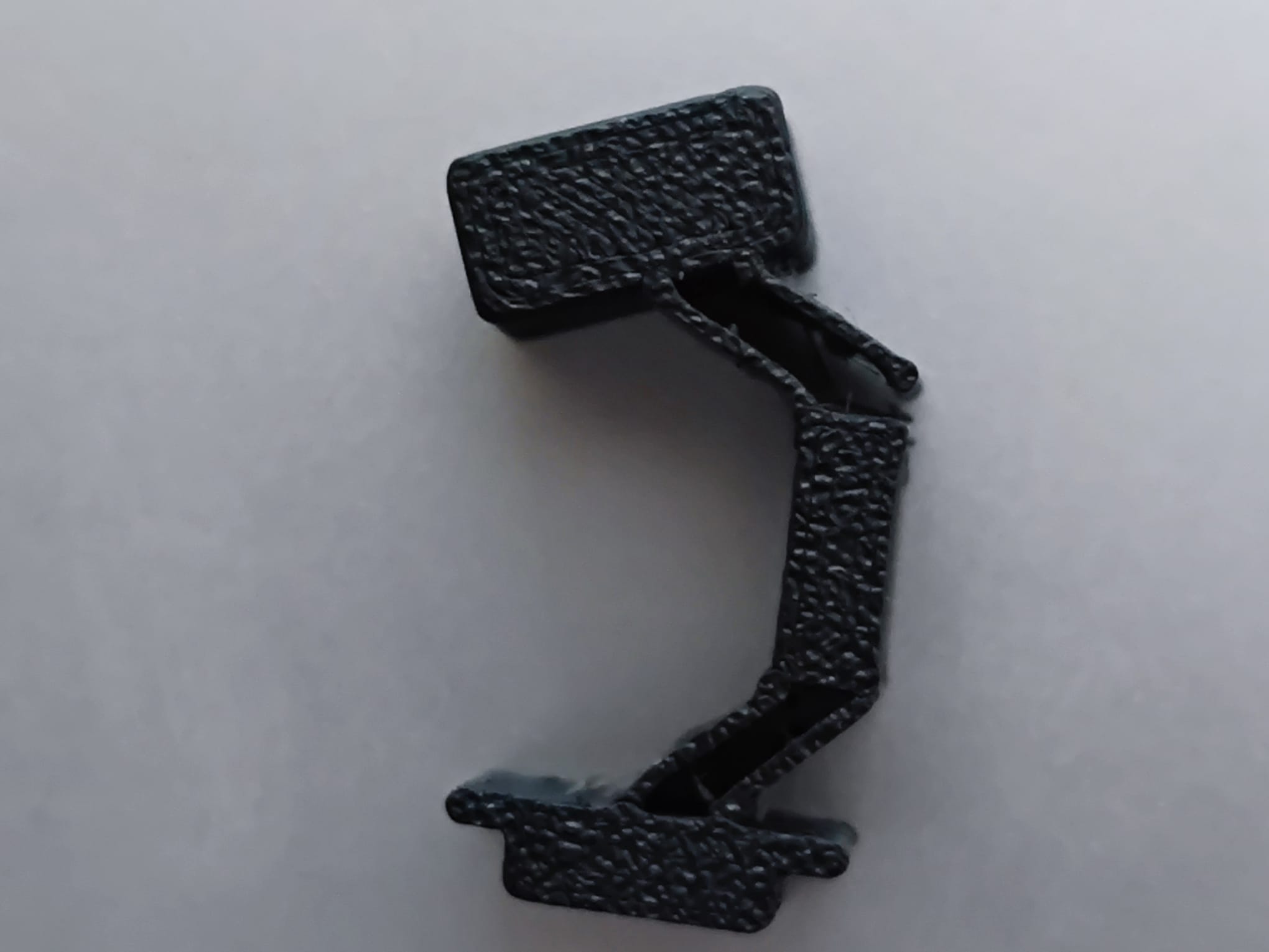
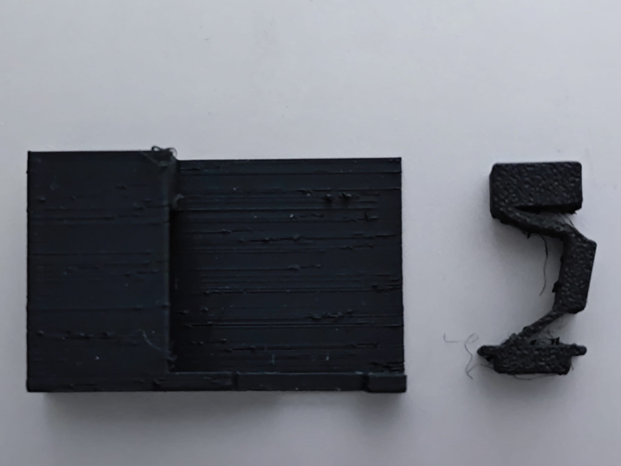
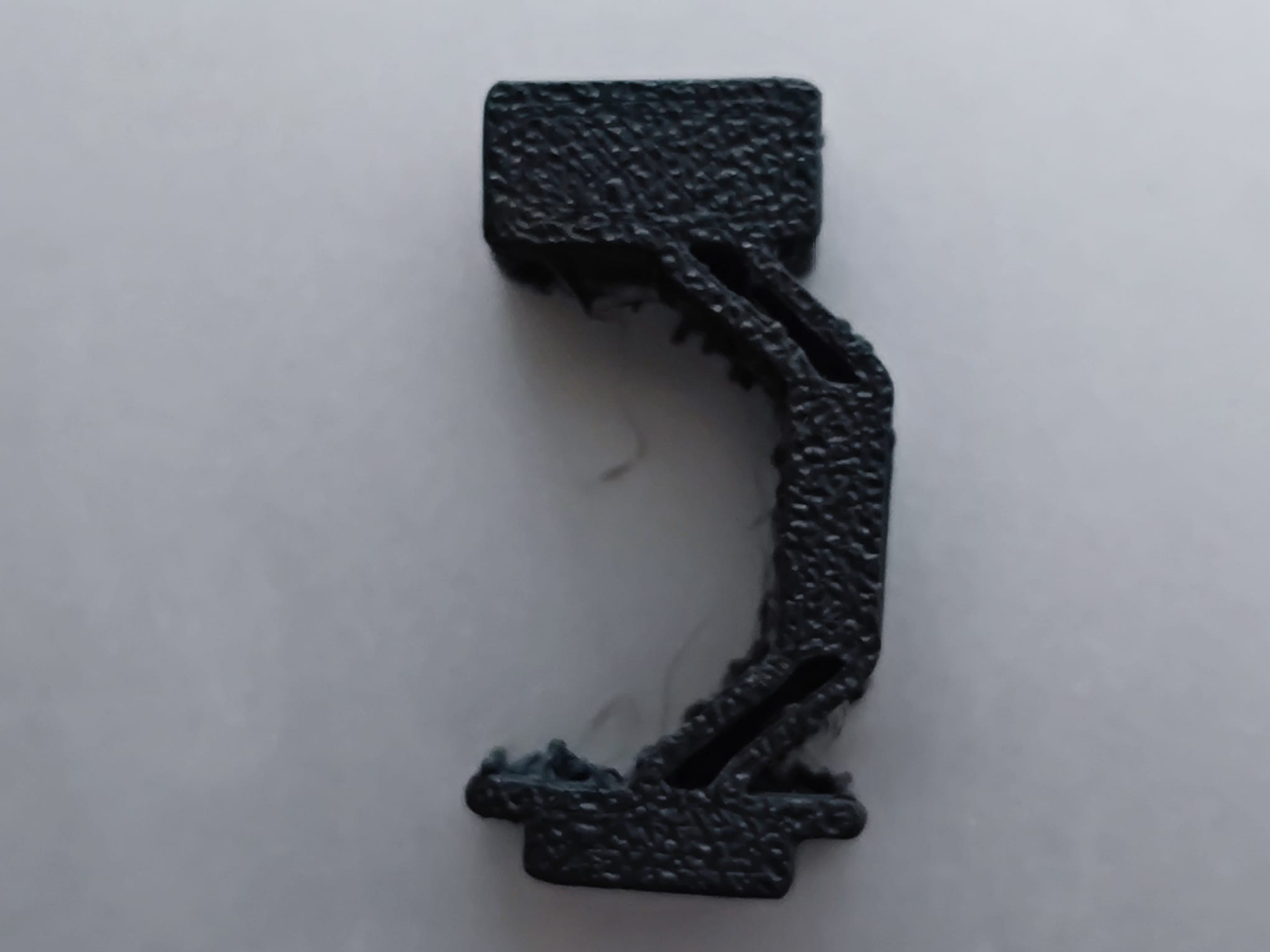
The print came off the bed just fine. I pressed on it, and it moved like I wanted it to. Excited, I pushed it into the housing and immediately broke a connector.
This effectively ended any chance of parallel-motion linkage. I pulled the MB out and noticed that it had snapped cleanly at the point of connection. I went back to my 3D printing slicer and checked how it had sliced things.
I use PrusaSlicer, and it was terminating all the lines at exactly the same connector location which needed the most structural strength. Varying the “seam position” didn’t help because these walls were too thin and the slicer just couldn’t figure out a path that didn’t terminate at the connection. I had to make the connectors thicker so it could print at least two lines, and therefore make a more solid connection.
Fourth print
PrusaSlicer recently added a mode called “Arachne” which lets the printer vary the thickness of the printed lines to give cleaner prints. My new design with a thicker connector was still resulting in single lines in the slicer. I disabled Arachne and managed to get dual lines in the slicer. New improvements:
- Sturdier connections
- Increased understanding of Slicers
This print was the sturdiest so far. Very little flex. I knew this was a risk when I increased the thickness, but I didn’t realize that this would make pressing the MB a workout.
I couldn’t flex the MB enough to put it into the housing, and I was worried that if I forced it, it would get stuck in the housing.
Fifth print
How do you increase flex when you have to also ensure sturdy connections? I was once again toying with the idea of using TPU. Maybe a new 3D printer with multi-material capabilities? Print connections in TPU, chunky parts in PLA? What could go wrong?
With renewed annoyance, I looked at the problem again. I didn’t actually need the connectors to be connected all the way. I needed them to be thick, but not tall. So I reduced the height of the connector and sent it off to print.
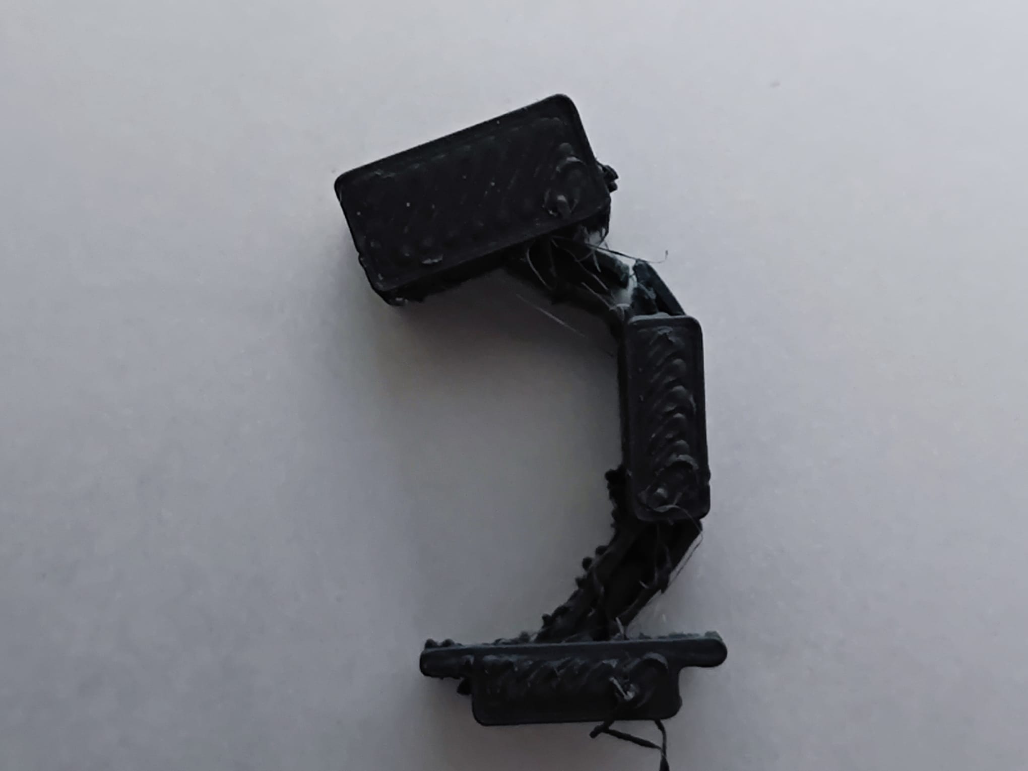
Once again, it looked good in print, and I wanted to check its flex. I pressed down and it snapped. Not at the now-sturdy connection points, but the connector itself.
At this point I decided that the first idea was a bust. I needed something reliable, that anyone could print and use consistently. I didn’t want a design that might accidentally work for me, but be extremely unreliable in the wild.
Idea 2
One of the things I didn’t want for this system was additional components. If I avoided adding a second button, but ended up adding a spring or metal clip, I wouldn’t have succeded in my goal.
Since the idea of an L-shaped crank would need a sturdy pivot, and that pivot would most likely have to be made of metal to be reliable, I decided to do the incline idea next, and leave the crank idea as a last measure.
I designed a new housing for this idea, and a new MB. I pushed the MB into the housing, and apart from a few tolerance issues that I could fix later, it seemed good.
Unfortunately the tolerances were really not great and I wasn’t getting enough feedback from the EB when I pressed the MB. Furthermore, the friction on the incline was too high for the EB to overcome, so when pressed, the EB stayed pressed.
Once again, I didn’t want a solution that meant a lot of post processing or luck. However, something incredible (incredibly stupid?) happened while I was playing around with this design. I realized that if I pressed on the housing while I held the component in place, it would click the button, and when I let go of the housing, it would un-click.
Bonus Idea 3
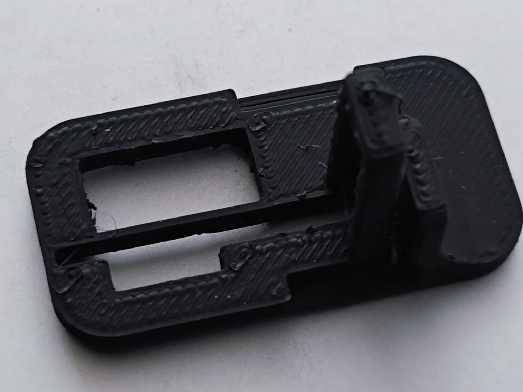
Armed with newfound faith in 3D printing, and realizing this “new” idea was quite similar to what I’d done before I set about designing a new housing that would combine both an MB and housing in once.
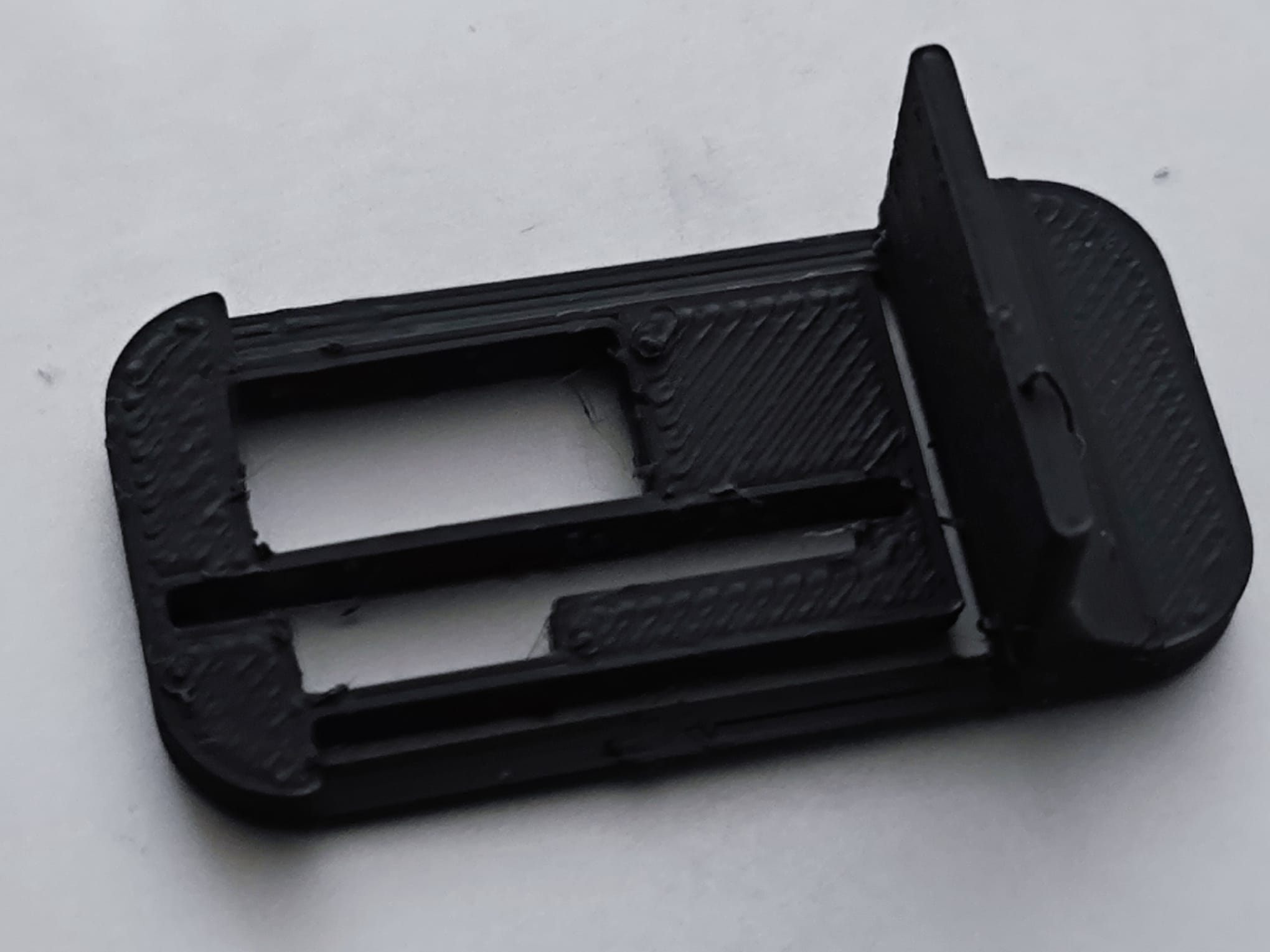
It worked great! Well, not great, but it worked! However there were improvements needed:
- Tolerances were too high
- Flex was too high
I fixed these and printed again.
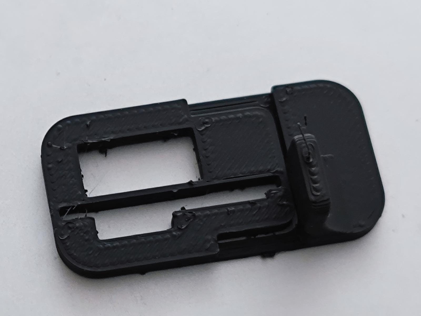
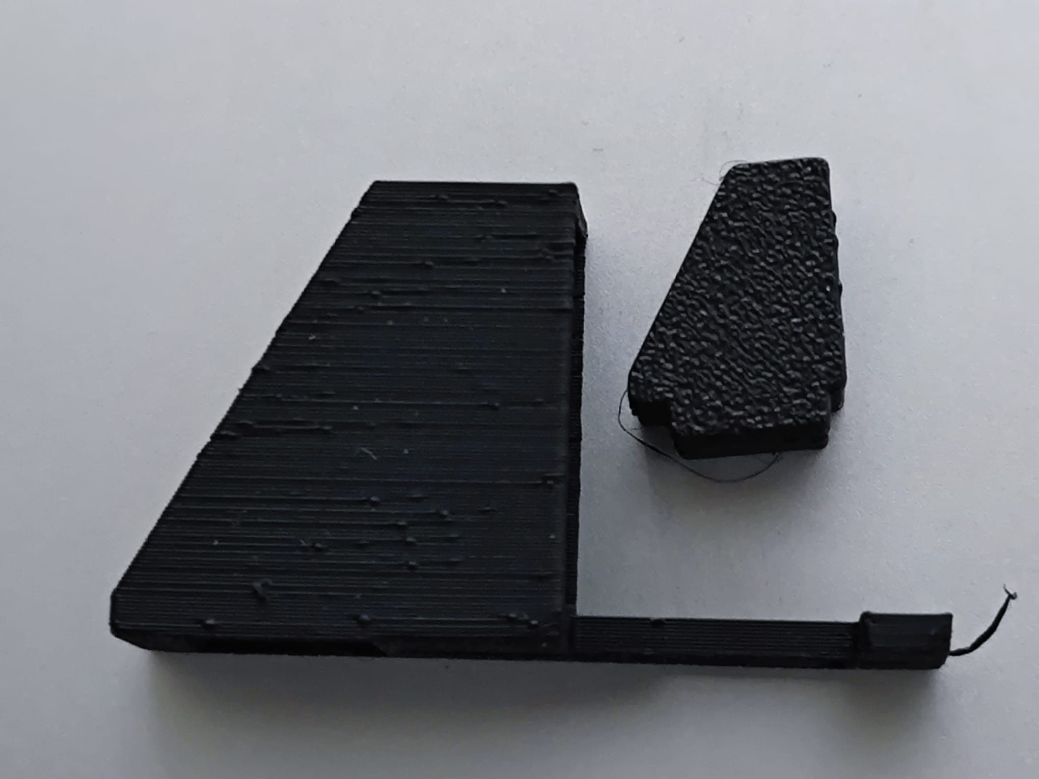
This actually worked great. The module fit snugly, and I could click the button perfectly. The only downside was that when I clicked, sometimes the component would slide a bit. I decided to make a bracket at the back to hold the module in place.
This was a disaster because the bridge on the bracket printed poorly, and the module wouldn’t even go into the housing. Deciding to go back and quit while I was ahead, I doubled down on the bracketless design. This isn’t an issue because everything gets superglued into place in the final object.
Conclusion
I redesigned the wood end cap for the Beacon with this new design, and it works great!
![]()
![]()
Perhaps tolerances can be tightened a bit more, and the MB placed closer to the module, but that’s a problem for another day!